There seems to be a few different ways to tackle this beast, so I'll just try to post up the suggestions in good format....
If you see something wrong with the information here, or want to add/change/delete some info, please let me know.
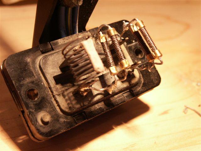
Resistance/Voltage readings on Block
Coils are in series.Smallest guage wire is coil A; coils B and C look about the same but about double the wire diameter.
(all resistance readings taken cold)
| Reference Table | Coil A | Coil B | Coil C | Total |
| Resistance | 1.1 ohm | 0.9 ohm | 0.7 ohm | 2.7 ohm |
| Speed 1 (lowest) | 3.1V | 2.0V | 1.4V | 6.5V |
| Speed 2 | 0.3V | 3.0V | 2.0V | 5.2V |
| Speed 3 | 0.2V | 0.1V | 2.9V | 3.2V |
| Speed 4 (highest) | 0.1V | 0.08V | 0.05V | 0.3V |
Electrical Technical Stuff
The best I was able to do was find my Excel calculations for the resistor values and wattages. Apparently Idid not commit my Digi-Key part numbers to a stored file, but I know I did put the information in a post, which
I guess is now lost to perpetuity. A real shame since a lot of work and time went into the results.
The calculations are based on Ed Rachner's measurements with a little fudge factor for some assumed contact
resistance in the measurements (learned from experience).
The last three lines of data are for whatever safety factor you want to design in (50%, 75%, and 100%) for the
wattage ratings. Actually the safety factors are much better than that, as the resistors are rated for wattage at
40° ambient air temperature without heat sinking rather than 25°C ambient - makes for a very conservative design.
Find the inexpensive square-body ceramic resistors in the DigiKey catalog (available on-line - www.digikey.com -
but, as most things are, it is much easier to browse thru using the hard copy) and use series and parallel
combinations to achieve the resistor values and wattage ratings (IIRC, the best choices happened to be
parallel combinations of the available values; also all individual resistors may have been 5W or 10W IIRC).
I believe going with 1.75 times the calculated wattage came out nicely to ganging several resistors of the
same value to achieve total resistance value very close to those required and wattage more than 1.75 times
those calculated (again, not including the fact that the resistor wattage ratings are for 40°C ambient).
If you need help with your calculations, several people here can give that. Basically, for parallel resistors
of the same value, divide the individual resistor value used by the number of resistors. For series of the
same value, multiply the individual resistor value used by the number of resistors. For wattage, multiply
the individual resistor wattage used by number of resistors. (Those calculations *only* work when all resistors
in a group are of the same value and wattage, and when all are either in parallel or all are in series - which,
as I said, is how it conveniently worked out for this application with the available resistors from Digi-Key.)
As stated in an earlier post in this thread, you theoretically could use more compact, "prettier" resistors
(with heat sinks) for a nicer package, but these ceramics are typically about $0.60US each vs. $3 to $5US each
for the nice ones. Plus, the nicer expensive ones are only readily available in a *very* limited selection of
lower resistance values that do not work out well for what's needed here.
THE REAL POOP (taken from Excel spread sheet):
Assumed measurement contact resistance (ohms): 0.05_ _ _ _
Assumed system voltage when measurements were made: 11.00 (Ed said he made his measurements with the engine off)
Assumed worst-case system voltage for wattage calculations: 14.00_ _ _ _
_ _ _ _ _ _ _ _ _ _ _ _
Measured resistance values (ohms): RA = 1.10, RB = 0.90, RC = 0.70
Assumed actual resistance: RA = 1.05, RB = 0.85, RC = 0.65
_ _ _ _ _ _ _ _ _ _ _ _
Worst-case voltage drop as measured: VA = 3.10, VB = 3.00, VC = 2.90
Worst case v. drop at assumed worst case system voltage: VA = 3.95, VB = 3.82, VC = 3.69
_ _ _ _ _ _ _ _ _ _ _ _
Calculated wattage requirement: WA = 14.83, WB = 17.15, WC = 20.96
Req'd wattage @ 1.5 x calculated: WA = 22.24, WB = 25.73, WC = 31.44
Req'd wattage @ 1.75 x calculated: WA = 25.94, WA = 30.01, WC = 36.68
Req'd wattage @ 2 x calculated: WA = 29.65, WB = 34.30, WC = 41.92
Digikey Part Numbers
(see www.digikey.com, then click "Catalog", then "Catalog Sections", then "Section F - Resistors...",then scroll to page 9 of 57 for the square ceramic resistors)
For RA (the low speed resistors), use three 3.0 ohm 10W resistors in parallel (gives theoretical 1.0 ohm,
conservative 30W; target was 1.05 ohms 26W).
Digi-Key P/N 3.0W-10-ND, qty. 3
For RB, use four 3.3 ohm 10W resistors in parallel (gives theoretical 0.825 ohms, conservative 40W;
target was 0.85 ohms 30W).
Digi-Key P/N 3.3W-10-ND, qty. 4
For RC, use five 3.3 ohm 10W resistors in parallel (gives theoretical 0.66 ohms, conservative 50W;
target was 0.65 ohms 37W).
Digi-Key P/N 3.3W-10-ND, qty. 5
(Note that RB and RC are built from the same resistor, so order 9 of those - actually you can get 10
cheaper than 9 because there's a price drop for 10.)
More Information
Coil A: Four 1.0 ohm 10W resistors, two in series, the other two in series, put the two series stringsin parallel. Result 1.0 ohm 40W.
(Digi-Key p/n 1.0W-10-ND)
Coil B: Four 3.3 ohm 10W resistors in parallel. Result 0.83 ohm at 40W
Coil C: Five 3.3 ohm 10W resistors in parallel. 0.66 ohm at 40W.
(Digi-Key p/n: 3.3-10-ND)
The whole thing cost about $8 to make-
I have enough resistors to build another. Instead of stacking the coils I might try to mount them in a
shallow rectangular project box, might be easier to mount underneath.
... And More Information
remember,as with most electrical systems
on a Subaru - it's a ground controlled system
This means the blower motor has battery positive
voltage any time the key is in the run position.
The switch and the resistor block control the
ground or negative side of the motor.
As Calebz correctly states (an item missed by many)
The switch by passes the resistor block in high speed.
It puts full ground on the motor.
I would pull the motor/squirrel cage down
and have a look for quests that may have built a home there.
Do this after checking to see if battery voltage is present.
if the relay/ power feed is to blame you will not have battery voltage
on the Green w/ white wire at the motor.
Please read this - there are three (3) fuses in the
fuse box that are required to make this system operate.
fuse # ----- power to
1 ------------blower relay contacts
2 ------------blower relay contacts (wired in parallel with #1)
12-----------blower relay control coil ( powered from ig sw.)
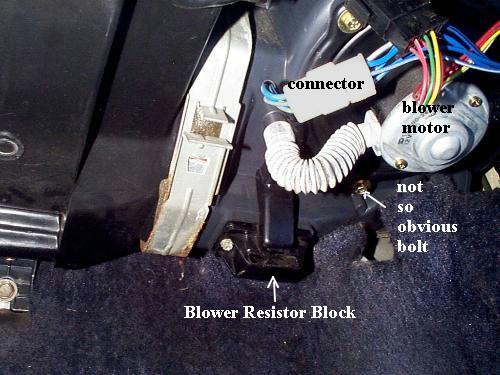
Here is where your resistors are.
... And More Information
I elected to tap into the mad scientist in myself and tackle this dilemma feet first. I found some5 watt ceramic coated resistors and decided to wire them in parallel, as SubSandRail suggested,
to keep the temps down. One of my OEM resistors, the one for fan position three, was intact. I needed
only to fix the ones for position one and two. I was shooting for .9 ohms for position two, and .7 ohm
for position one. I purchased two 1.8 ohm resistors, and couldn't find two 1.4 ohm so I ended up with two
1.2 ohm units for fan position one. Wiring them in parallel would halve those ratings, yielding .9 and .6 respectively.
The first order of business was to take a hammer, and smash the ceramic coatings off. They were too bulky,
and I thought they would not let the resistors cool fast enough in the airflow.
Here's one of each of the resistors (I used two of each).

Then I soldered them in parallel, and soldered them into the resistor block. I plugged them in, held the block
in my hand and turned on the fan. In position three, the OEM resistor got hot enough to glow. When I held it
up to the airflow, however, the glowing ceased as it cooled rather quickly. The same for my two in position
two. The glowed pretty good, but didn't under the airflow. Position one didn't glow much at all. There is a
metal casing they mount into in the air duct, so with that and the airflow of the fan, I'm not too worried about
it. Of course, the wife has instructions to immediately select position four if she smells anything burning.
How much am I saving on this? Is it worth the headache? I'm not sure at this point.
The resistors cost $2.00 total, so that saved about $62.00. The block is easy to get to thanks to the awesome
photo I found on this site. I can tell I'm going to be spending a lot of time here. Here is a photo of the
finished, soldered project. I had to twist the resistors I fashioned into a more diagonal orientation to get
them to fit inside the stock duct opening. Of course, do this at your own peril.
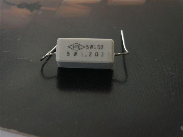
Update. The resistors in position two failed in about 2 hours. I replaced them with a different brand, but
still 1.8 ohm 5 watt resistors. The NTE resistors are of a larger diameter once the ceramic is removed,
and will (I hope) dissipate the heat better. They look like this: (Pictured is a 1.2 ohm but the 1.8's look the same)
Pics of a "Homebuilt" pack


Wiring Diagram from FSM

And Another Method...
the coils on my resistor were broken i used 20 ga , 30 ga saftey wire to make new ones and
soldered works grate all speeds are back